
In industrial automation and machine control, standard relays and general-purpose programmable controllers are strictly prohibited from managing critical life-safety functions. When an operator strikes an Emergency Stop pushbutton, opens an interlocked guard door, or breaks a safety light curtain, the circuit must de-energise reliably—even if a physical contact welds shut or a cable is crushed.
This deterministic reliability is provided by Category 4 / Performance Level e (Cat 4 / PL e) safety relays.
Representing the highest standard of functional safety under BS EN ISO 13849-1 and BS EN 62061 / BS EN 60204-1, these devices provide redundant, self-monitoring control that ensures no single hardware fault or accumulation of faults leads to the loss of the safety function.
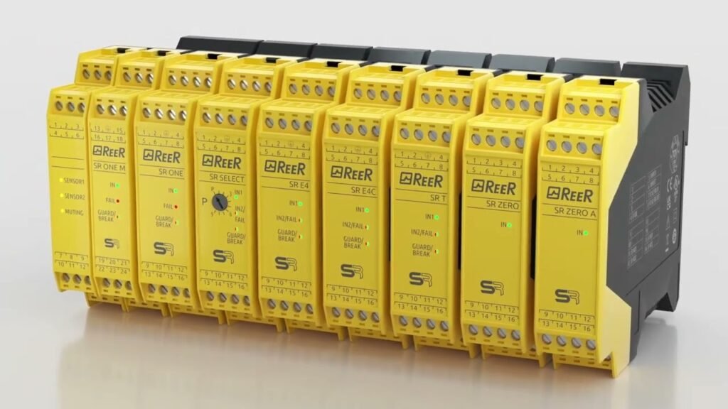
1. What Do “Category 4” and “PL e” Actually Mean?
While often referenced together on yellow-cased safety modules (such as Pilz PNOZ, Schneider Preventa, or Sick modules), Category 4 and Performance Level e derive from different parts of the safety standard BS EN ISO 13849-1:
┌─────────────────────────────────────────────────────────────────────────────┐
│                 FUNCTIONAL SAFETY STANDARDS (BS EN ISO 13849-1)             │
├──────────────────────────────────────┬──────────────────────────────────────┤
│ Category 4 (Architecture)            │ Performance Level e (Probability)    │
├──────────────────────────────────────┼──────────────────────────────────────┤
│ Deterministic structure              │ Statistical probability of failure   │
│ Redundant dual-channel paths         │ Probability of dangerous failure per │
│ Comprehensive internal diagnostics   │ hour: PFH_D < 10⁻⁷ (less than 1 in   │
│ Fault detection before or at next run│ 10 million operating hours)          │
└──────────────────────────────────────┴──────────────────────────────────────┘
- Category 4 (Design Architecture): Dictates how the circuit is physically built. It mandates that a single fault (e.g., welded contact, short circuit to 24V, earth fault) will not cause a loss of the safety function. Furthermore, that single fault must be detected at or before the next demand on the safety system. If detection does not occur, an accumulation of undetected faults must not compromise safety.
- Performance Level e (PL e): Represents the highest statistical integrity tier on a scale from PL a (lowest) to PL e (highest). It is determined by evaluating four key metrics:
- Category (Structure): Must be Category 4 architecture.
- MTTF$_D$ (Mean Time to Dangerous Failure): High ($>30\text{ years}$, up to $100\text{ years}$).
- DC$_{avg}$ (Diagnostic Coverage): High ($\ge 99\%$ of potential dangerous faults are actively detected).
- CCF (Common Cause Failure): Measures taken against shared vulnerabilities (e.g., physical channel separation, overvoltage protection).
2. Core Internal Architecture: Why a Safety Relay Cannot “Fail On”
A common industrial relay uses a single electromagnetic coil to pull a set of spring-loaded contacts. If high arcing current causes those contacts to weld together, cutting power to the coil will not open the circuit.
A Category 4 safety relay prevents this through three core internal design principles:
                  ┌────────────────────────────────────────┐
                  │       24V DC REDUNDANT SUPPLY          │
                  └───────────┬────────────────┬───────────┘
                              │                │
                      Channel 1 (S11/S12)   Channel 2 (S21/S22)
                              │                │
                              ▼                ▼
                     ┌──────────────────────────────────┐
                     │   CROSS-MONITORING LOGIC CORE    │
                     │  (Microprocessors or Force-      │
                     │   Guided Internal Relays K1/K2)  │
                     └────────────────┬─────────────────┘
                                      │
                         ┌────────────┴────────────┐
                         ▼                         ▼
                  ┌──────────────┐          ┌──────────────┐
                  │  Output K1   │          │  Output K2   │
                  │  (Contact 1) │          │  (Contact 2) │
                  └──────┬───────┘          └──────┬───────┘
                         └────────────┬────────────┘
                                      ▼
                        SERIES-WIRED SAFETY OUTPUTS
                           (Terminals 13 - 14)
1. Force-Guided Contacts (Mechanically Linked)
Internal relays adhere to EN 50205 (Type A). The normally open (NO) switching contacts and normally closed (NC) monitoring contacts are mechanically interlinked on a single rigid carrier:
- If an output NO contact welds closed, the corresponding NC contact cannot close mechanically, maintaining an air gap of at least 0.5mm.
- The relay’s internal logic detects that the monitoring contact is open and completely locks out the start/reset circuit, preventing the machine from ever re-starting.
2. Redundant Dual-Channel Processing
The relay features two independent internal circuits (Channels K1 and K2). Both channels must be energized simultaneously to close the safety outputs. If one internal channel fails, the second channel safely drops the load.
3. Cross-Fault Detection & Pulse Testing
The relay feeds dynamic test pulses (clocked square waves) out of its channel terminals (typically S11 and S21):
- If an external cable is pinched and Channel 1 shorts directly into Channel 2, or shorts to an external +24V rail, the relay detects the mismatched pulse timing in milliseconds.
- The relay trips into an immediate fault state and inhibits restart until the short is removed.
3. Standard Cat 4 / PL e Wiring & Terminal Conventions
Achieving a true Category 4 / PL e loop requires correct field wiring practices from the input device to the final actuators:
┌─────────────────────────────────────────────────────────────────────────────┐
│                 COMPLETE CAT 4 / PL e ARCHITECTURAL LOOP                    │
├─────────────────────────────────────────────────────────────────────────────┤
│ Dual-Contact Input     ──► Dual-Channel Relay    ──► Dual Force-Guided Contactor│
│ (2x NC Contacts)           (Cross-Monitored)         (EDM Feedback Loop via Y1-Y2)│
└─────────────────────────────────────────────────────────────────────────────┘
- Dual-Channel Input Device: The Emergency Stop or safety gate switch must have two mechanically independent, normally closed (NC) positive-break contacts. One contact wires between S11–S12, the other between S21–S22.
- External Device Monitoring (EDM / Feedback Loop):
- A safety relay cannot directly switch a large 45kW motor; it switches auxiliary safety contactors (KM1 and KM2).
- To maintain PL e, the normally closed (NC) auxiliary contacts of both external contactors are wired in series back into the reset loop (Y1–Y2).
- If contactor KM1 welds shut under load, the Y1–Y2 loop remains open. When an operator tries to reset the safety relay, it detects the open feedback circuit and denies energisation.
- Manual Monitored Reset: Cat 4 systems require a manual reset pushbutton configured for a falling-edge transition. If the reset button jams closed or is tampered with (“tied down” with tape), the relay will not reset.
4. When is a Cat 4 / PL e Safety Relay Required?
Under the UK Supply of Machinery (Safety) Regulations and ISO 12100, the machine designer must perform a formal Risk Assessment using the ISO 13849-1 risk graph:
               ┌── F1 (Rare exposure) ────────► PL b / PL c
      ┌── S1 ──┤
      │        └── F2 (Frequent exposure) ────► PL c / PL d
Risk ─┤
      │        ┌── F1 ── P1 (Avoidable) ──────► PL c / PL d
      └── S2 ──┤        └── P2 (Unavoidable) ──► PL d / PL e
               │
               └── F2 ── P1 (Avoidable) ──────► PL d / PL e
                        └── P2 (Unavoidable) ──► PL e (Cat 4 Required)
- Severity of Injury (S):
S1= Reversible injury (minor cuts, bruising).S2= Irreversible injury or death (amputation, fatal crush).
- Frequency / Exposure Time (F):
F1= Seldom to less often, short exposure time.F2= Frequent to continuous exposure (e.g., loading parts every minute).
- Possibility of Avoiding Hazard (P):
P1= Possible under specific conditions.P2= Scarcely possible (rapid, unexpected machine movements).
Where a hazard results in S2 + F2 + P2 (such as high-speed robotic cells, hydraulic stamping presses, timber guillotines, and automated palletisers), Category 4 / PL e is mandatory.
Frequently Asked Questions (FAQ)
Can I wire single-channel inputs to a Category 4 safety relay?
No. Wiring a single-channel switch into a safety relay immediately downgrades the safety architecture to Category 1 or 2. If that single wire shorts to 24V or the switch contact fails mechanically closed, the safety function is entirely bypassed. Category 4 strictly demands dual-channel inputs with cross-fault monitoring.
What is the difference between a Safety Relay and a Safety PLC?
A Safety Relay is a dedicated, single-function hardware unit configured via physical wiring—ideal for machines with 1 to 4 safety zones. A Safety PLC is a software-programmable, multi-processor controller certified to SIL 3 / PL e, designed to coordinate complex multi-zone factories, safety networking (e.g., PROFIsafe), and light curtain muting routines.
What happens if an external contactor welds closed in a Cat 4 system?
Because the safety contactors (KM1 and KM2) are wired in series, the healthy contactor will still open and cut main three-phase power to the motor, safely stopping the hazard. The welded contactor’s auxiliary NC contact breaks the External Device Monitoring (EDM) loop, preventing the safety relay from resetting until the damaged contactor is replaced.
Why are safety relays coloured yellow?
While not an explicit legal standard, industrial equipment manufacturers universally use bright yellow housings (or occasionally red) to distinguish life-safety modules from general-purpose blue or grey automation gear. This ensures panel builders, commissioning engineers, and maintenance personnel do not modify or cross-wire critical safety circuits during modifications.
High-Specification Components for Compliant Control Panels
Building safety circuits to BS EN ISO 13849-1 and BS EN 60204-1 requires dependable materials—from dedicated Red AC and Dark Blue DC control conductors to precision insulated bootlace ferrules that eliminate loose stranding faults.
Source your BS 6231 Tri-Rated cable, panel accessories, and crimping tools with fast UK delivery at Panelwire.co.uk.